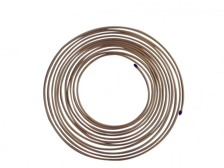
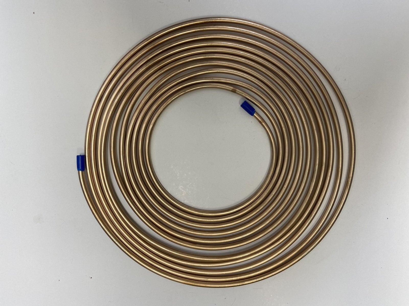
CuNiFer (Copper-Nickel-Iron) brake line tube is the premier material for hydraulic brake and fuel line applications in automotive, commercial vehicle, and off-highway equipment. The alloy — nominally 90% Copper, 6% Nickel, and 4% Iron (Fe) with trace manganese — was developed specifically to overcome the severe corrosion limitations of traditional Bundy (steel) brake tubing, particularly in road-salt environments.
Supplied as precision seamless tube coils in standard lengths of 25, 50, and 100 metres, CuNiFer brake line tubing is pre-coated with a polymer protective layer in many OEM applications, and can be bent, flared, and double-flared on-site using standard automotive tooling. It is approved by all major automotive OEMs and is the material of choice for European and North American vehicle manufacturers.
The nominal Cu90/Ni6/Fe4 composition is optimised for automotive brake line service — balancing corrosion resistance, strength, and formability. Controlled per ISO 4038 and DIN 74234 material specifications.
| Element | Symbol | Min (%) | Max (%) | Role in Braking System Performance |
|---|---|---|---|---|
| Copper | Cu | Balance | Balance | Matrix — provides excellent formability, conductivity, and corrosion base in wet environments |
| Nickel | Ni | 5.0 | 7.0 | Primary corrosion resistance element — forms stable protective oxide film; resists road salt attack |
| Iron | Fe | 3.5 | 5.5 | Critical for erosion-corrosion resistance under high-velocity hydraulic fluid flow; strengthens matrix |
| Manganese | Mn | 0.3 | 0.8 | Deoxidiser; improves hot workability and tube drawing performance; scavenges sulphur |
| Lead | Pb | — | 0.02 | Controlled impurity; low levels required for automotive RoHS and ELV (End of Life Vehicle) compliance |
| Zinc | Zn | — | 0.30 | Trace impurity limit |
| Carbon | C | — | 0.05 | Trace impurity limit |
| Sulphur | S | — | 0.02 | Trace impurity limit |
* Composition per ISO 4038 Table 1 / DIN 74234. RoHS 2 (2011/65/EU) and ELV Directive (2000/53/EC) compliant — lead below threshold. All values weight percent.
Standard brake line tube sizes follow ISO 4038, DIN 74234, and SAE J1047. All dimensions in millimetres unless stated. Custom ODs and wall thicknesses available on request for OEM projects.
| OD (mm) | OD (inch) | Wall Thickness (mm) | ID (mm) | Flow Area (mm²) | Weight (kg/m) | Primary Application |
|---|---|---|---|---|---|---|
| 3.18 | 1/8" | 0.71 | 1.76 | 2.43 | 0.053 | Instrument & sensor lines |
| 4.00 | — | 0.71 | 2.58 | 5.23 | 0.068 | Small bore metric lines |
| 4.75 | 3/16" | 0.71 | 3.33 | 8.71 | 0.082 | Standard passenger car brake lines (most common) |
| 4.75 | 3/16" | 0.89 | 2.97 | 6.93 | 0.099 | Heavy duty / high-pressure passenger car |
| 6.00 | — | 0.71 | 4.58 | 16.48 | 0.105 | Larger passenger & light commercial vehicles |
| 6.00 | — | 1.00 | 4.00 | 12.57 | 0.142 | Heavy duty light commercial |
| 6.35 | 1/4" | 0.71 | 4.93 | 19.07 | 0.111 | Light truck & SUV brake mains |
| 6.35 | 1/4" | 1.00 | 4.35 | 14.86 | 0.151 | Heavy duty light truck |
| 8.00 | 5/16" | 1.00 | 6.00 | 28.27 | 0.194 | HGV / truck brake mains & chassis lines |
| 8.00 | 5/16" | 1.25 | 5.50 | 23.76 | 0.237 | Heavy truck high-pressure circuits |
| 10.00 | 3/8" | 1.00 | 8.00 | 50.27 | 0.246 | Large HGV and bus brake main supply lines |
| 10.00 | 3/8" | 1.50 | 7.00 | 38.48 | 0.355 | Off-highway high-pressure braking |
| 12.00 | — | 1.00 | 10.00 | 78.54 | 0.298 | Agricultural & construction equipment |
| 12.70 | 1/2" | 1.25 | 10.20 | 81.71 | 0.388 | Heavy off-highway brake supply |
Density of CuNiFer: 8.9 g/cm³. OD tolerance: ±0.05 mm. WT tolerance: ±0.04 mm per ISO 4038. Most common automotive size is 4.75 mm OD × 0.71 mm WT.
| SAE Size | SAE OD (inch) | OD (mm) | WT (mm) | ISO 4038 Ref. | DIN 74234 Ref. | Thread / Fitting Type |
|---|---|---|---|---|---|---|
| — | — | 4.75 | 0.71 | Series A | Type A | M10×1 / ISO 7 Banjo |
| 3/16" | 0.1875" | 4.76 | 0.028" (0.71) | Series A | Type A | 3/16" SAE double flare |
| 1/4" | 0.250" | 6.35 | 0.028" (0.71) | Series B | Type B | 7/16"-24 UNF / M12×1 |
| 5/16" | 0.3125" | 7.94 | 0.028" (0.71) | Series C | — | 1/2"-20 UNF |
| 3/8" | 0.375" | 9.53 | 0.035" (0.89) | Series D | Type D | 9/16"-18 UNF / M14×1.5 |
| Property | Value | Unit | Condition / Notes |
|---|---|---|---|
| Density | 8.9 | g/cm³ | At 20°C |
| Melting Range | 1100 – 1150 | °C | Liquidus to solidus |
| Tensile Strength (min) | 380 | MPa | Cold drawn, ISO 4038 / DIN 74234 |
| Yield Strength 0.2% (min) | 275 | MPa | Cold drawn condition |
| Elongation (min) | 25 | % | 50 mm gauge; required for double-flare forming |
| Vickers Hardness (HV) | 120 – 165 | HV | Cold drawn; within flarability range |
| Elastic Modulus | 125 | GPa | At room temperature |
| Thermal Conductivity | ~40 | W/m·K | At 20°C |
| Thermal Expansion Coeff. | 17.0 | ×10⁻⁶/°C | Mean 20–300°C |
| Min Bend Radius | 3 × OD | — | Cold bend, no mandrel; 2.5× with mandrel |
| Compatibility — DOT 3 Fluid | Fully Compatible | — | No swelling, no corrosion, no contamination |
| Compatibility — DOT 4 Fluid | Fully Compatible | — | Standard automotive brake fluid |
| Compatibility — DOT 5 (silicone) | Fully Compatible | — | Racing and military applications |
| Compatibility — Mineral Oil (LHM) | Fully Compatible | — | Citroën/Rolls-Royce hydraulic systems |
| Max Continuous Operating Temp. | 150 | °C | In brake fluid service; above caliper area |
| Min Operating Temp. | −55 | °C | No embrittlement at sub-zero temperatures |
| RoHS / ELV Compliance | Yes | — | Pb <0.01%; meets 2000/53/EC and 2011/65/EU |
Calculated per ISO 4038 and DIN 74234. Burst pressure is the minimum hydraulic pressure at which the tube fails; working pressure applies a safety factor of 4. Standard automotive braking systems operate at 100–180 bar peak.
| OD (mm) | WT (mm) | ID (mm) | Min Burst Pressure (bar) | Safety Factor | Allow. Working Press. (bar) | Typical System Press. (bar) | Safety Margin |
|---|---|---|---|---|---|---|---|
| 4.75 | 0.71 | 3.33 | 700 | 4× | 175 | 150–180 | ~4.0× |
| 4.75 | 0.89 | 2.97 | 880 | 4× | 220 | 150–180 | ~5.0× |
| 6.00 | 0.71 | 4.58 | 548 | 4× | 137 | 100–150 | ~4.5× |
| 6.00 | 1.00 | 4.00 | 773 | 4× | 193 | 100–150 | ~6.0× |
| 6.35 | 0.71 | 4.93 | 516 | 4× | 129 | 100–150 | ~4.3× |
| 6.35 | 1.00 | 4.35 | 729 | 4× | 182 | 100–150 | ~5.8× |
| 8.00 | 1.00 | 6.00 | 575 | 4× | 144 | 80–120 | ~5.5× |
| 8.00 | 1.25 | 5.50 | 720 | 4× | 180 | 80–120 | ~7.0× |
| 10.00 | 1.00 | 8.00 | 460 | 4× | 115 | 60–100 | ~5.0× |
| 10.00 | 1.50 | 7.00 | 690 | 4× | 173 | 60–100 | ~8.0× |
| 12.70 | 1.25 | 10.20 | 480 | 4× | 120 | 60–80 | ~7.0× |
Burst pressure formula: P = (2 × S × WT) / OD where S = tensile strength (MPa). Min burst per ISO 4038: 700 bar for 4.75×0.71 mm. All pressure values in bar (1 bar = 14.5 psi = 0.1 MPa).
Understanding why CuNiFer is the preferred choice over Bundy steel, stainless steel, and nylon/polymer brake lines for OEM and replacement applications.
| Material | Salt Spray Hours (no red rust) | Condition After 500 hrs | Typical Field Life (salt-belt roads) | Failure Mode |
|---|---|---|---|---|
| CuNiFer (bare) | > 500 hrs | Light surface tarnish only; no corrosion | 25 – 40 years | Physical damage only |
| CuNiFer (nylon coated) | > 1000 hrs | No change; coating intact | 35+ years | Coating abrasion |
| Bundy steel (bare) | < 24 hrs | Heavy red rust; structural loss | 3 – 8 years | Perforation corrosion |
| Bundy steel (galvanised) | 48 – 96 hrs | Red rust through coating | 5 – 12 years | Pitting under coating |
| Stainless steel SS316 | > 1000 hrs | No corrosion | 50+ years | Fatigue / fitting failure |
| Nylon PA12 | N/A (non-metallic) | No corrosion | 15 – 25 years | UV degradation / cracking |
A complete step-by-step technical guide for automotive technicians, fleet maintenance engineers, and OEM assembly personnel working with CuNiFer brake tube coils.